Get "10 RF Design Principles Every Engineer Should Know" Free
Learn practical principles for better RF circuits, PCB layouts, simulations, measurements, and troubleshooting.

Understand the practical link between antenna Q factor and bandwidth, including compact antenna limits, matching, efficiency, and validation.
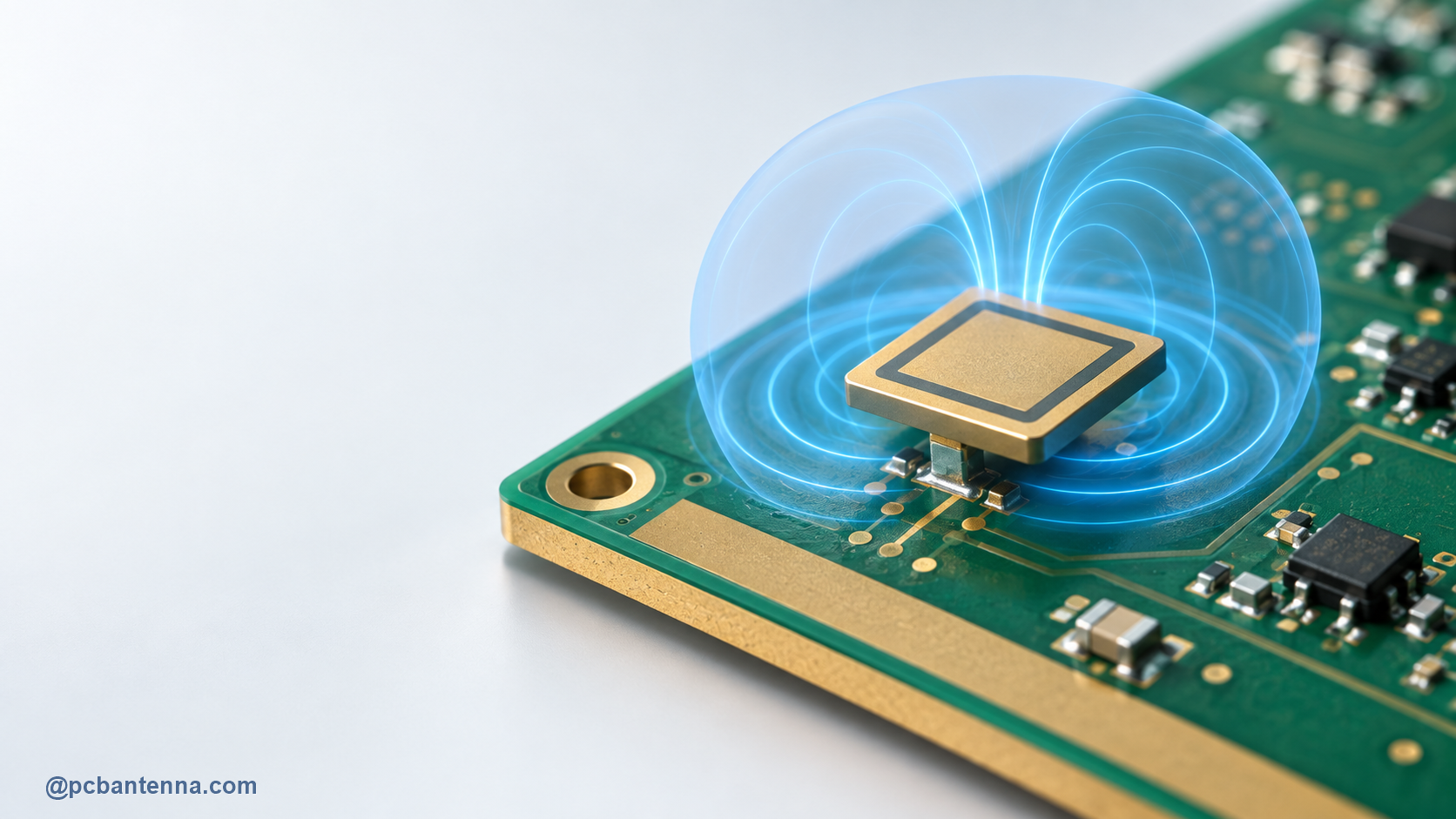
Antenna Q factor is a useful way to think about why small antennas often have limited bandwidth. In simple terms, Q relates stored energy to energy lost or radiated per cycle. A high-Q resonant system tends to have a sharper, narrower response. A lower-Q system tends to have a broader response, though the full antenna story also includes radiation efficiency, matching, geometry, and the product environment.
As an antenna becomes electrically small for its operating wavelength, it often stores a larger proportion of energy around the radiator relative to the energy it radiates. That can make its impedance response more sensitive and its usable bandwidth narrower. The effect is not a layout mistake. It is one of the constraints designers work with when fitting a radio into a small product.
This is why a tiny antenna may need careful matching and still offer less margin than a larger structure. If the enclosure or a battery shifts the resonance, a narrowband design may move out of the required operating range more easily.
For a simple resonant system, bandwidth and Q are often described as inversely related. That idea is useful, but a real PCB antenna is not an isolated ideal resonator. Ground plane size, matching network, losses, multiple resonances, dielectric materials, and mechanics all shape the measured response.
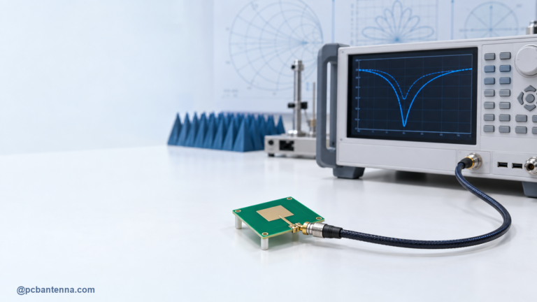
Be careful with an apparently broad S11 curve. Loss can broaden a match without improving radiated efficiency. When you compare two designs, include efficiency or gain data where possible, not just the width of the return-loss dip.
Multiple resonant paths, slots, and carefully chosen ground structures can broaden a response, but they introduce their own tradeoffs. They may affect pattern, efficiency, tuning sensitivity, or mechanical integration. Use a narrow, well-defined sweep rather than changing several features at once. See parametric sweep optimization for PCB antenna bandwidth for a practical method.
Ask whether the required band can be covered by the available antenna volume with usable efficiency. If the answer is uncertain, compare antenna types, board positions, or enclosure options early. It is usually less expensive to add a little antenna volume during mechanical design than to discover at the end that a tiny radiator needs an unrealistic tuning solution.
When the product uses a compact chip antenna, treat the supplier’s reference board as a starting point rather than a transferable guarantee. The chip antenna integration guide explains why host board and enclosure details matter so much.
During a review, ask which variable is actually limiting the design. If resonance is in the wrong place, geometry, feed position, or the surrounding dielectric may be the priority. If the match covers the band but range is weak, investigate efficiency, orientation, and nearby losses. If the bare board works but the product does not, focus on the enclosure, battery, cable, and use condition. Separating those questions keeps Q factor from becoming a vague explanation for every RF problem.
It also helps to record a small set of acceptance results for every revision: the required-band S11 trace, the chosen matching values, the housing configuration, and one radiated comparison. Those records make it easier to see whether a later mechanical change reduced margin, even when the antenna trace was never edited.
A final Q or bandwidth discussion needs final hardware. Measure the antenna with its production-like housing, battery, and cable arrangement. Compare required-band coverage, not only center-frequency match. Follow with radiated tests if the product depends on a certain range or orientation.
Q factor is most helpful when it changes the design conversation from “Why will this not match everywhere?” to “What volume, bandwidth, efficiency, and tuning margin can this product realistically support?” For help making that decision, contact PCB Antenna.