Get "10 RF Design Principles Every Engineer Should Know" Free
Learn practical principles for better RF circuits, PCB layouts, simulations, measurements, and troubleshooting.

Use focused parametric sweeps to improve PCB antenna bandwidth while keeping geometry, mesh convergence, efficiency, and manufacturability in view.
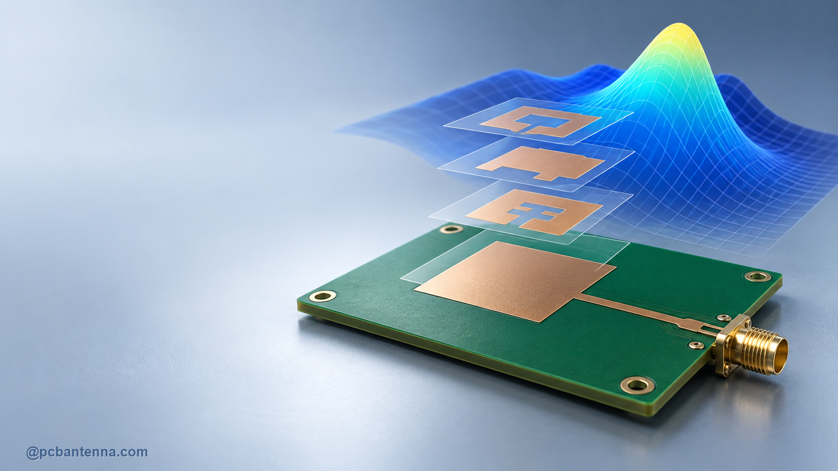
A parametric sweep is one of the most useful ways to turn antenna simulation into an engineering decision. Instead of changing one dimension, solving once, and guessing what to try next, you define a small set of variables and let the model show how each choice moves resonance, bandwidth, impedance, and sometimes radiation behavior.
The key word is small. A sweep becomes unhelpful when every dimension, material property, and boundary setting is allowed to vary at once. Good optimization begins with a clear target and a short list of dimensions that have a believable physical connection to that target.
Before creating variables, write down what the antenna needs to do. Is the target a minimum return-loss level over a narrow channel group, a wider operating band, a specific center frequency, or a compromise between match and efficiency? State the reference impedance and measurement condition too. Without that, an optimizer can improve a curve that is not actually connected to the product requirement.
Keep a baseline result from the unmodified design. Record its resonant frequency, S11 shape, usable band, and one or two far-field metrics. You will need it later to decide whether an apparent improvement is genuine or simply moved the problem elsewhere.
Start with two or three variables. Use a range that manufacturing and mechanical constraints can realistically support. If a simulated optimum requires an impractically narrow gap or a component value with no tuning margin, it is not yet a product solution.
A coarse sweep reveals direction. It can show whether increasing radiator length moves the resonance down, whether a slot has a strong effect, or whether the matching network is doing most of the work. Once you see the trend, narrow the range around a promising area and use a smaller increment.
This two-stage approach is easier to review than a giant grid of nearly identical results. It also helps you catch unexpected behavior. If two variables interact strongly, use a focused two-dimensional sweep and examine the response surface instead of assuming the effects add independently.
Every point in a sweep needs a simulation setup that is valid across the selected range. Ansys documents that adaptive meshing may use a single frequency, multiple frequencies, or a broadband approach. For an antenna bandwidth study, check that the adaptation strategy supports the band you are judging. A sweep is only as reliable as the mesh and setup behind each result.
Use convergence checks before treating a narrow optimum as meaningful. A shallow difference in S11 can disappear after additional mesh refinement or after the enclosure is added. See HFSS mesh convergence for antenna projects for a structured review method.
A wider match is not automatically a better antenna. Check efficiency, peak gain, relevant directions, current distribution, and sensitivity to tolerances. A geometry can look excellent in S11 while creating an undesirable null in the direction that matters to the device.
Build realistic materials and mechanics into later sweeps. Include solder mask if it is close to the radiator, preserve the intended ground cutout, and compare the board with representative enclosure parts. For a PCB antenna, the board and housing are not optional decoration around the model.
Use the results to choose a nominal geometry with tuning margin, not an overly precise virtual answer. Keep the matching network accessible, make the selected dimensions easy to fabricate, and order prototypes that can distinguish the important variables. Then compare measured S11 and radiation behavior with the model.
The antenna bandwidth improvement guide can help frame the available tradeoffs. For a custom sweep plan or simulation review, contact PCB Antenna.