Get "10 RF Design Principles Every Engineer Should Know" Free
Learn practical principles for better RF circuits, PCB layouts, simulations, measurements, and troubleshooting.

Plan LTE and cellular antenna placement in compact devices with practical guidance on clearance, feed routing, coexistence, mechanics, and final validation.
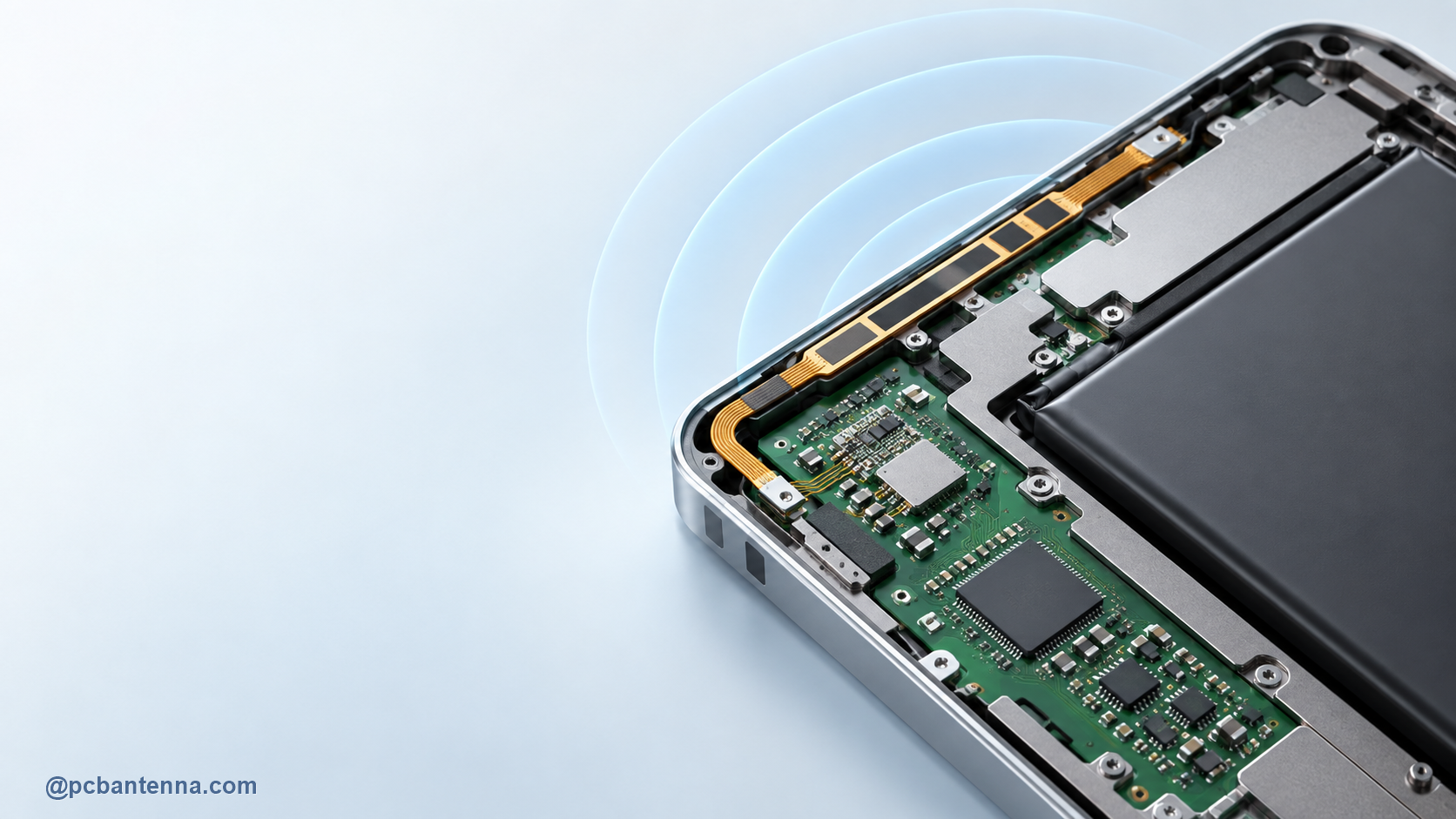
Cellular antenna placement in a compact device is usually a system integration task rather than a simple component placement task. The antenna must work across its intended bands while sharing space with battery cells, displays, cameras, shields, speakers, cables, and other radios. A layout that looks tidy can still create a poor RF environment if the antenna is boxed in by nearby metal or placed in the wrong product orientation.
Cellular designs may need to cover several frequency bands, and the selected antenna has a specific reference layout, ground requirement, clearance zone, and feed arrangement. Confirm the exact supported bands and the supplier’s test conditions before committing to the mechanical design. An antenna optimized for one range may not have the margin needed for another.
Consider whether the product needs a board-mounted antenna, flex antenna, cable-fed antenna, or external antenna. The choice should reflect the available clearance, ground plane, enclosure materials, expected orientation, and production assembly process. A different antenna type may be a better solution than trying to force an unsuitable one into a crowded corner.
Reserve the antenna region in the PCB and mechanical CAD models. Keep batteries, metal frames, shield cans, screws, speakers, display brackets, and cables away according to the antenna supplier’s integration requirements. Do not allow a late mechanical change to erase the required clearance.
Reference layouts commonly place board antennas at an edge or corner and protect their no-copper zone on all layers. The exact dimension belongs to the selected antenna data sheet. The general workflow is covered in antenna keepout area layout rules.
Route the RF feed as a controlled-impedance path using the actual board stackup. Keep it short, direct, and away from switching power and digital aggressors. Place the recommended matching network close to the antenna feed, with accessible tuning options if the supplier recommends them.
Avoid using extra feed length as a convenient routing path. At cellular frequencies, it is part of the RF network. Vias, bends, discontinuities, and a broken return path all affect the result. Review 50-ohm PCB feed-line design before final routing.
Compact devices often carry Bluetooth, Wi-Fi, GNSS, NFC, or other radios near the cellular antenna. Treat antenna separation, frequency overlap, ground return, and cable routing as a coexistence review. Test radio combinations, not only one transmitter at a time.
Also test the intended user and installation conditions. A handheld device, tracking unit, gateway, or industrial sensor will see different nearby materials and orientations. The enclosure and battery detuning guide is relevant whenever final mechanics shift the antenna response.
Cellular performance can change when a cable supplier changes, a battery pack moves a few millimeters, a metal bracket is added, or an adhesive position changes. Treat these as RF-relevant changes in the product release process. Capture the approved antenna placement, cable route, matching network, and enclosure parts in drawings and build notes so that a later revision does not quietly remove the margin created during tuning.
When the product will be built at scale, compare representative units rather than relying on a single hand-tuned sample. A robust design is one that maintains the required bands and reasonable radiated performance across normal material and assembly variation. This is especially important when an antenna is integrated into a tight mechanical stack.
A compact cellular design benefits from early coordination between RF, PCB, mechanical, and product teams. For an engineering review of a multi-radio product, contact PCB Antenna.