Get "10 RF Design Principles Every Engineer Should Know" Free
Learn practical principles for better RF circuits, PCB layouts, simulations, measurements, and troubleshooting.

Learn antenna polarization, linear and circular fields, cross-polarization, and mismatch loss so you can make better RF design decisions.

Antenna polarization is the orientation and motion of an electromagnetic wave’s electric field as it travels away from an antenna. It sounds abstract at first, but it has a very practical consequence: two antennas can be tuned to the same frequency and still communicate badly if their polarizations do not match. That is why polarization belongs in the same early design conversation as frequency, bandwidth, ground plane, and enclosure.
This guide explains linear and circular polarization, the role of cross-polarization, and how polarization mismatch loss can quietly reduce a link budget. The aim is not to turn every antenna choice into a theory exercise. It is to give you a reliable way to choose, describe, and test polarization in a real product.
In the far field, an antenna radiates electric and magnetic fields that are perpendicular to each other and to the direction of travel. Polarization normally refers to the electric-field component. If that field stays in one fixed direction, the wave is linearly polarized. If its tip rotates as the wave propagates, the wave is circularly or elliptically polarized.
The important word is orientation. A vertically mounted antenna is not automatically vertically polarized in every direction, and a PCB trace that looks horizontal does not automatically create a horizontally polarized field at the receiver. The installed ground plane, feed, nearby metal, enclosure, and the observation direction all influence the final result. This is one reason simulation and measurement should happen in the actual product configuration, not only on an isolated PCB.
With linear polarization, the electric field remains on a single line. The familiar examples are vertical and horizontal polarization. A vertical monopole above a suitable ground plane is commonly treated as vertically polarized in the horizontal directions around it. A horizontal dipole, viewed broadside to the wire, is commonly treated as horizontally polarized.
Linear polarization is often a sensible choice when the orientation of both antennas is known and stable. Fixed point-to-point links, panel antennas, and a product that always sits in one position can benefit from that predictability. It is also straightforward to check: rotate the receiving antenna, watch received power or S21, and note the angle where the signal is strongest and weakest.
The catch is orientation sensitivity. For two ideal, linearly polarized antennas, the polarization loss factor is proportional to cos²(theta), where theta is the angle between their polarization directions. At a 90-degree mismatch, the idealized link has no polarization coupling. Real devices are less tidy because reflections and cross-polarized fields can add a little energy back, but the signal reduction can still be dramatic.
A circularly polarized wave is made from two orthogonal linear field components with equal amplitude and a 90-degree phase difference. As the wave moves forward, the electric-field vector traces a circle. If the amplitudes are unequal or the phase difference is not exactly 90 degrees, the path becomes an ellipse instead. In practice, every circularly polarized antenna has some imperfection, so engineers use axial ratio to describe how close it is to a perfect circle. An ideal circular wave has an axial ratio of 1, or 0 dB.
Circular polarization can help when the relative orientation between transmitter and receiver changes. This is useful in satellite links, GNSS, rotating platforms, and some wireless products that may be held or installed in unpredictable orientations. A circularly polarized antenna still needs careful validation: its useful bandwidth, axial ratio, radiation pattern, and gain may not peak at the same frequency.
You will also see RHCP and LHCP, short for right-hand and left-hand circular polarization. The naming convention depends on the stated viewing direction, so documentation should always say which convention is being used. Antennas with opposite circular senses are ideally isolated from each other, but reflections can reverse the sense of circular polarization. That is a useful property in some systems and an important warning in multipath-heavy environments.
Cross-polarization is the unwanted orthogonal polarization component radiated or received by an antenna. For a vertically polarized antenna, the horizontal component is cross-polarized. Low cross-polarization is usually desirable because it preserves the intended polarization and improves isolation between channels that reuse the same frequency with orthogonal polarizations.
For PCB antennas, cross-polarization often grows when the ground plane is asymmetric, the feed transitions are poor, the enclosure is close, or cables and nearby structures become accidental radiators. A radiation-pattern plot can look acceptable in one cut and reveal a strong unwanted component in another. When possible, inspect co-polar and cross-polar plots in both principal planes, then compare them with the mechanical configuration you will actually ship.
For two ideal linear antennas, the quick estimate is simple: calculate the polarization loss factor as the square of the cosine of the orientation error. Convert that factor to dB with -10 log10(PLF). A 45-degree error produces about 3 dB of loss, while a 90-degree error is an ideal null. This is separate from free-space path loss, cable loss, and impedance mismatch, so it belongs as its own line item in a link budget.
A linearly polarized antenna communicating with a perfectly circularly polarized antenna has a theoretical 3 dB polarization loss, because the linear antenna receives one of the circular wave’s two equal components. The real number may differ because of axial ratio, angle, reflections, and the actual antenna patterns. Treat the simple values as first-pass engineering estimates, then confirm the product with a realistic measurement.
When you are building the rest of the link budget, use the RF Link Budget Calculator alongside the Free Space Path Loss Calculator. For frequency-dependent geometry, the Wavelength Calculator and Antenna Length Calculator are useful early checks. They do not replace a full electromagnetic model, but they keep the first design decisions grounded in scale.
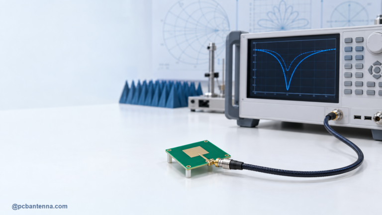
It is easy to confuse a good match with good polarization. S11 and return loss tell you how much power reflects at the antenna feed. Polarization tells you how well the radiated field aligns with the receiving antenna. You need both. An antenna can show an excellent S11 notch on a VNA and still perform poorly across the link because the antennas are cross-polarized, the enclosure changes the pattern, or the device is being held in a different orientation.
For PCB work, the physical layout still matters. A clean feed, sensible ground-plane clearance, and room for tuning can make the difference between an antenna that behaves consistently and one that changes with every enclosure revision. The Microstrip Patch Antenna Design Guide is a useful follow-up for a planar antenna example, and our antenna design services are available when the product needs a measured, system-level review.
Choose polarization to match the real use case, not just the drawing on the PCB. Linear polarization is efficient and predictable when orientation is controlled. Circular polarization is valuable when orientation changes, provided you validate axial ratio and handedness. In either case, treat cross-polarization, mismatch loss, radiation pattern, and S11 as separate checks. That fuller view catches failures long before they become a range problem in the final product.