Get "10 RF Design Principles Every Engineer Should Know" Free
Learn practical principles for better RF circuits, PCB layouts, simulations, measurements, and troubleshooting.

Practical GNSS antenna placement guidance for small PCBs, including sky view, ground plane, noise separation, RF feed, and final-device testing.

GNSS antenna placement is not just a PCB routing decision. A receiver needs extremely weak satellite signals, so the antenna’s view of the sky, its local ground environment, and the noise generated by the rest of the product all matter. On a small PCB, those constraints arrive at the same time as batteries, displays, processors, and enclosures.
Ask how the product will be used before deciding where the GNSS antenna goes. A patch antenna typically needs to face the sky in the intended orientation. A device that lies flat, is mounted vertically, or is worn on the body may need a different antenna type or placement strategy. u-blox highlights that antenna position and a clear line of sight to satellites are central to GNSS performance.
A small board does not remove that requirement. It simply makes placement choices more consequential. Put the antenna where the product enclosure and normal orientation give it the best opportunity to see the sky, rather than where it is most convenient to route.
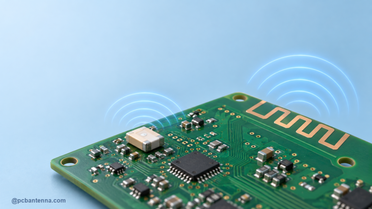
A ceramic patch antenna, active external antenna, flexible antenna, or compact chip antenna can all be appropriate depending on the product. Patch antennas often need a defined ground relationship and favorable orientation. Active antennas can help when cable loss or receiver noise figure is a concern, but they add power and integration requirements. A tiny chip antenna saves space only when its reference layout and clearance can be respected.
Do not select solely by the quoted gain figure. Check the intended band, required ground plane, polarization, feed, matching network, enclosure clearance, and expected use orientation. The antenna and receiver front end must be evaluated as a system.
GNSS bands are sensitive to local interference. Keep the antenna and its feed away from switching regulators, high-speed clocks, display cables, memory buses, and noisy power inductors. Use a clean controlled-impedance feed and follow the selected antenna’s reference layout. Avoid routing digital signals under an antenna keepout just because the top layer looks clear.
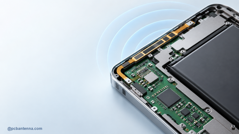
Nearby metal can block or redirect signals and may detune compact antennas. Battery packs, shields, screws, and flex cables need a mechanical review as well as an electrical one. The antenna keepout guide applies directly here: protect the clearance on all relevant layers and in the enclosure.
Follow the ground-plane and feed recommendations for the exact GNSS antenna. A patch antenna may need a ground plane beneath it, while a chip antenna may need a defined no-copper area. Those are not interchangeable instructions. Keep the matching components close to the feed and use the footprint values the vendor specifies as a starting point.
Use a controlled 50-ohm route where the design calls for it, and avoid unplanned vias or sharp routing changes. Read 50-ohm PCB trace design for antenna feeds before choosing a trace width from a generic online chart.
Measure the antenna match on the assembled device, then run real GNSS acquisition and tracking tests in an appropriate outdoor or controlled environment. Compare time to first fix, satellite visibility, carrier-to-noise results where available, and performance across orientations. Ensure the test is fair: the same location, sky view, firmware, and power state make comparisons meaningful.
Do not expect an indoor desk test to represent final GNSS performance. Building materials, windows, and multipath can dominate the result. Start with antenna placement that respects the product orientation, then use outdoor validation to confirm the design.
For help reviewing a GNSS or multi-radio product layout, contact PCB Antenna.