Get "10 RF Design Principles Every Engineer Should Know" Free
Learn practical principles for better RF circuits, PCB layouts, simulations, measurements, and troubleshooting.

Learn the real difference between dB, dBi, and dBd, how to convert dBd to dBi, and what gain reference to use in antenna comparisons and link budgets.
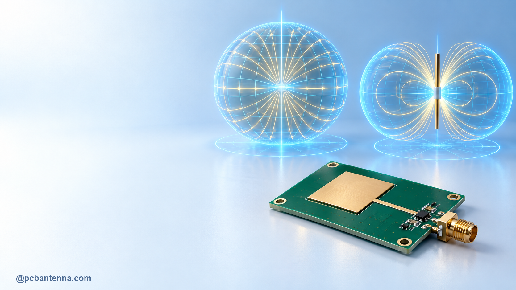
dB, dBi, and dBd look almost identical on a datasheet, but they do not mean the same thing. The difference is small in spelling and large in engineering. A plain dB value is a ratio. dBi is antenna gain referenced to an ideal isotropic radiator. dBd is antenna gain referenced to a half-wave dipole. Mixing them can make an antenna comparison look 2.15 dB better or worse than it really is.
This guide explains dBi vs dBd vs dB in practical RF terms, shows the conversion, and covers the details to check before using a gain number in a PCB antenna design or a link budget.
dB, or decibel, is a logarithmic way to express a ratio. It does not identify an absolute power level or a particular antenna reference by itself. In RF work, dB is commonly used for gains and losses through cables, filters, matching networks, amplifiers, or a propagation path.
For a power ratio, use:
dB = 10 log10(P2 / P1)
For voltage or current ratios in the same impedance, use 20 log10(V2 / V1) or 20 log10(I2 / I1). That distinction matters because power is proportional to the square of voltage when impedance is unchanged. A 3 dB power increase is close to twice the power. A 3 dB loss is close to half. The same dB notation lets a link budget add gains and subtract losses without repeatedly multiplying large and small linear numbers.
dBi means decibels relative to an isotropic radiator. An isotropic radiator is an ideal reference that radiates equally in every direction. It is not a physical antenna you can buy, but it gives engineers a consistent zero-gain reference. A value of 0 dBi means the peak gain equals the isotropic reference. A value of 6 dBi means the peak directional gain is 6 dB above that reference.
Most modern antenna specifications use dBi. Keysight describes dBi as antenna gain in decibels relative to an isotropic radiator, and IEEE’s Technology Navigator likewise uses dBi for that reference. It is the clearest default for a link budget because free-space formulas and many RF tools use the isotropic reference directly.
Remember that dBi is directional. A 6 dBi antenna does not provide 6 dB more signal everywhere around the product. It has a peak direction, along with lower-gain areas and often deep nulls. Review the radiation pattern before turning one peak number into a coverage claim.
dBd means decibels relative to a half-wave dipole. A free-space half-wave dipole has approximately 2.15 dBi of peak gain. Therefore, the two units differ by 2.15 dB:
Gain(dBi) = Gain(dBd) + 2.15 dB
And in the opposite direction:
Gain(dBd) = Gain(dBi) – 2.15 dB
For example, an antenna rated at 3 dBd is approximately 5.15 dBi. The antenna did not change. Only the reference changed. This is the source of many accidental comparison errors: a 3 dBd antenna should not be compared directly with a 3 dBi antenna as though the values are equivalent.
| Value | Meaning | Equivalent reference |
|---|---|---|
| 0 dB | No change in a power ratio | Reference depends on the two values being compared |
| 0 dBi | Peak gain equal to an isotropic reference | -2.15 dBd |
| 0 dBd | Peak gain equal to a half-wave dipole reference | 2.15 dBi |
| 5 dBi | Peak gain 5 dB above isotropic | 2.85 dBd |
| 8 dBd | Peak gain 8 dB above a dipole | 10.15 dBi |
The table applies to the same measurement or simulation conditions. It does not correct for different frequencies, antennas mounted above different ground planes, mismatch, cable loss, or different test environments. Those details can be much larger than the 2.15 dB reference conversion.
A gain figure does not mean the antenna amplifies signal by itself. A passive antenna redistributes the available radiated energy. Higher gain normally comes with a more focused pattern. That can be useful for a point-to-point link, but it can reduce coverage in directions outside the main lobe.
For a compact PCB antenna, the published or simulated number also depends on the board, ground plane, feed, nearby plastic, metal, battery, and enclosure. A standalone antenna module may have a respectable peak dBi value on a reference board and a completely different result in the final device. The PCB ground-plane guide explains why this happens so often.
HFSS can report directivity, gain, and realized gain. They should not be treated as aliases. Directivity describes the pattern concentration. Gain includes radiation loss. Realized gain additionally includes input mismatch, making it especially helpful when you want an antenna-plus-feed result for a practical design.
Before comparing two HFSS results, keep the frequency, coordinate system, polarization, source condition, and normalization choice consistent. Then check the S11 curve, efficiency, peak value, and pattern together. The HFSS S11 setup guide and far-field radiation-pattern setup guide show how those pieces connect.
A simple link budget adds transmitter power and antenna gains, then subtracts path and implementation losses:
Pr(dBm) = Pt(dBm) + Gt(dBi) + Gr(dBi) – path loss(dB) – other losses(dB)
The gain terms should be dBi when the equation uses the isotropic-reference form. If a supplier gives dBd, convert it first. “Other losses” may include cable loss, connector loss, polarization mismatch, fading margin, and packaging effects. A link budget is a useful estimate, not permission to ignore room reflections, antenna orientation, or receiver sensitivity.
You can use the RF and antenna calculators to explore wavelength and free-space path-loss relationships, then place the actual antenna gain and known losses into the system budget.
Use plain dB for a ratio or system loss. Use dBi for gain referenced to an isotropic radiator. Use dBd for gain referenced to a half-wave dipole, then convert to dBi before making an isotropic-reference link budget. The 2.15 dB difference is simple, but the operating frequency, radiation pattern, efficiency, and finished-product layout are just as important. For a deeper gain walkthrough, read Antenna Gain Formula Explained. For help with PCB antenna layout or validation, contact PCB Antenna.