Get "10 RF Design Principles Every Engineer Should Know" Free
Learn practical principles for better RF circuits, PCB layouts, simulations, measurements, and troubleshooting.

Understand the practical difference between VSWR, return loss, and S11, how they relate, and which RF metric to use in antenna testing.
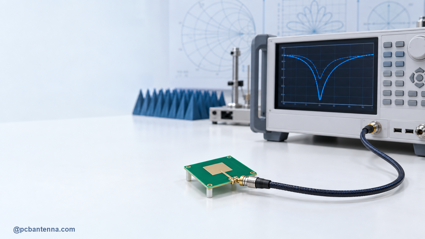
VSWR, return loss, and S11 are often used in the same conversation because they all describe reflection at an RF port. They are related, but they are not interchangeable labels. Knowing the difference makes it easier to read a VNA plot, compare an antenna data sheet, and explain what changed after a tuning revision.
When a source, transmission line, and load have the same reference impedance, power can transfer with minimal reflection. When the load does not match, part of the incident wave returns toward the source. At an antenna port, that mismatch can come from the antenna geometry, ground plane, enclosure, feed layout, or matching network.
The complex reflection coefficient, commonly written as Gamma, describes the reflected wave relative to the incident wave. S11 is the name used for the input reflection coefficient of port 1 in an S-parameter measurement. A VNA measures S11 as a complex quantity with magnitude and phase. That is the underlying measurement from which familiar scalar plots are derived.
S11 is usually plotted in dB on an antenna chart. More negative values indicate less reflected power at that port. An S11 curve shows where the antenna system is best matched, how wide the matched region is, and whether multiple resonances exist. It does not directly tell you gain, efficiency, or range. An antenna can show a nice S11 minimum while still losing energy in nearby objects or resistance.
Always check the reference impedance, calibration method, connector quality, and measurement setup before comparing one S11 chart with another. A different reference plane can make a clean-looking comparison misleading.
Return loss expresses the same mismatch magnitude as a positive dB number. It is based on the ratio of forward to reflected power. Higher return loss means a smaller reflected portion and therefore a better impedance match. An ideal mathematical match has infinite return loss; a complete reflection corresponds to 0 dB return loss.
That sign convention is the usual source of confusion. If an S11 graph says minus 10 dB, the equivalent return loss is 10 dB. The physical measurement is the same. The chart is simply using a different presentation.
VSWR, or voltage standing-wave ratio, expresses mismatch as a ratio. It is calculated from the magnitude of the reflection coefficient: VSWR equals (1 plus magnitude of Gamma) divided by (1 minus magnitude of Gamma). A perfect match is 1:1. As mismatch increases, the ratio rises.
VSWR is convenient on a requirement sheet because it is intuitive to compare with a limit. It is less convenient than S11 when you want to see a deep resonance because the scale expands rapidly near a poor match. Use whichever form makes the decision clearest, but do not mix the numbers without converting them correctly.
For a practical antenna review, record all three only if different stakeholders need them. Otherwise, use S11 for the detailed plot and state the acceptance criterion clearly in the same units. The S11 and return-loss guide offers a deeper measurement walkthrough.
Matching tells you how the feed sees the load. It is not a complete wireless performance score. Check radiation pattern, efficiency, polarization, enclosure effects, and the final use environment as well. A deliberately lossy antenna can sometimes look well matched because loss absorbs energy that was not radiated.
When you are choosing a target, start with the radio, band, and antenna supplier recommendation. Some product teams use a simple 2:1 VSWR limit as a screening point, but a valid target is still application-specific. Confirm it through link-budget and product testing rather than treating one number as universal.
For quick preliminary calculations, visit the RF and antenna calculators. For a PCB antenna that will not settle into the expected band, review the ground plane, feed, and keepout area before changing components at random.