Get "10 RF Design Principles Every Engineer Should Know" Free
Learn practical principles for better RF circuits, PCB layouts, simulations, measurements, and troubleshooting.

Learn how to check HFSS mesh convergence for PCB antenna projects, choose adaptation frequencies, and validate S11 and far-field results.

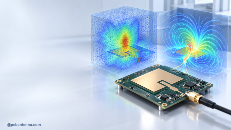
HFSS can produce a very convincing antenna plot long before the model is trustworthy. A smooth S11 curve, a colorful far field, and a finished solve are useful, but they do not automatically prove that the mesh has settled. Mesh convergence is the check that tells you whether a later adaptive pass is still changing the answer enough to matter.
For a PCB antenna project, convergence is especially important because small features can control the result. The feed, matching pads, narrow trace sections, slots, vias, solder mask, and nearby enclosure details can all create strong local fields. A coarse model may miss those effects, while an unnecessarily dense model can waste a great deal of solve time. The goal is not the biggest mesh. It is a model whose important results stop moving for sensible engineering reasons.
Before looking at Delta S, verify the model itself. Use the real board stackup where possible, assign material properties deliberately, define the port in a way that matches the feed, and keep radiation boundaries far enough from the antenna for the chosen solver setup. A mesh cannot repair an incorrect reference plane, missing ground cutout, or unrealistic enclosure.
Choose outputs before you solve. For a narrowband antenna, that may mean S11 at the operating band and realized gain in a few important directions. For a broadband antenna, include the full impedance response and radiation behavior across the intended range. This keeps the review focused on decisions that affect the product rather than every available graph.
HFSS refines the mesh through adaptive passes. One common stopping metric is Maximum Delta S, the change in S-parameters between consecutive adaptive solutions. A small Delta S is useful evidence that the port response is stabilizing. Ansys also supports single-frequency, multi-frequency, and broadband adaptive strategies. The right choice depends on whether one frequency or an entire band is critical to the design.
Do not treat a single pass that meets a loose target as a final answer. Open the convergence history and compare the final few passes. Look for a stable resonance frequency, stable minimum S11, and stable impedance around the band edge. If the final point is still drifting, either tighten the target, allow more passes, or inspect the model for a feature that needs more attention.
A single adaptive frequency can be appropriate when the antenna is narrowband and the important behavior is centered around one known frequency. It is less reassuring for a design that must work over a broad band, has multiple resonances, or includes a wide matching requirement. In those cases, multi-frequency or broadband adaptation can provide a better basis for the sweep.
The important detail is that a frequency sweep does not automatically force the mesh to be equally good everywhere. Set adaptation frequencies around the actual engineering question: the target channel, the edge of a required operating band, or the resonances that will be tuned. For practical S11 setup guidance, see how to set up S11 simulation for a PCB antenna in HFSS.
Automatic adaptation is often sufficient, but manual mesh guidance can help when you already know where the model is sensitive. Typical candidates are an extremely narrow feed, a small gap in the matching network, a slot edge, a fine via transition, or a sharp current concentration. Add refinement only where it has a purpose. Blanket refinement can make the solve slower without making the antenna result more reliable.
Compare at least two sensible mesh strategies when the design is important. For example, run the default adaptive model, then run a second model with a targeted refinement around the feed and matching area. If the resonance, input match, and key radiation outputs stay close, confidence improves. If they change materially, investigate rather than averaging the two answers.
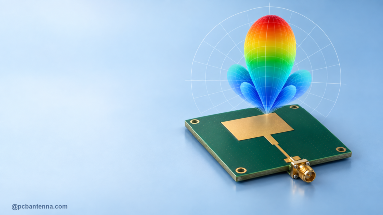
S11 convergence is necessary but not always sufficient. A model can show a stable input match while the far-field pattern, efficiency estimate, or peak direction still changes. Review the final two or three passes for the outputs that matter to the product. When the device will be mounted near a battery, cable, or housing, include those parts in a separate comparison run before declaring the design done.
Far-field checks are easier to interpret when the setup is consistent. Our HFSS far-field radiation-pattern guide covers the reporting side of that workflow.
Convergence is not a badge that the solver awards. It is evidence you build by checking whether the outputs that drive your decision remain stable. When simulation and measurement disagree, revisit the model assumptions first, then the mesh, then the prototype setup. For an RF design review or simulation support, contact PCB Antenna.