Get "10 RF Design Principles Every Engineer Should Know" Free
Learn practical principles for better RF circuits, PCB layouts, simulations, measurements, and troubleshooting.

A practical Wi-Fi antenna design guide covering antenna types, gain, directionality, placement, PCB layout, multiband integration, and validation.
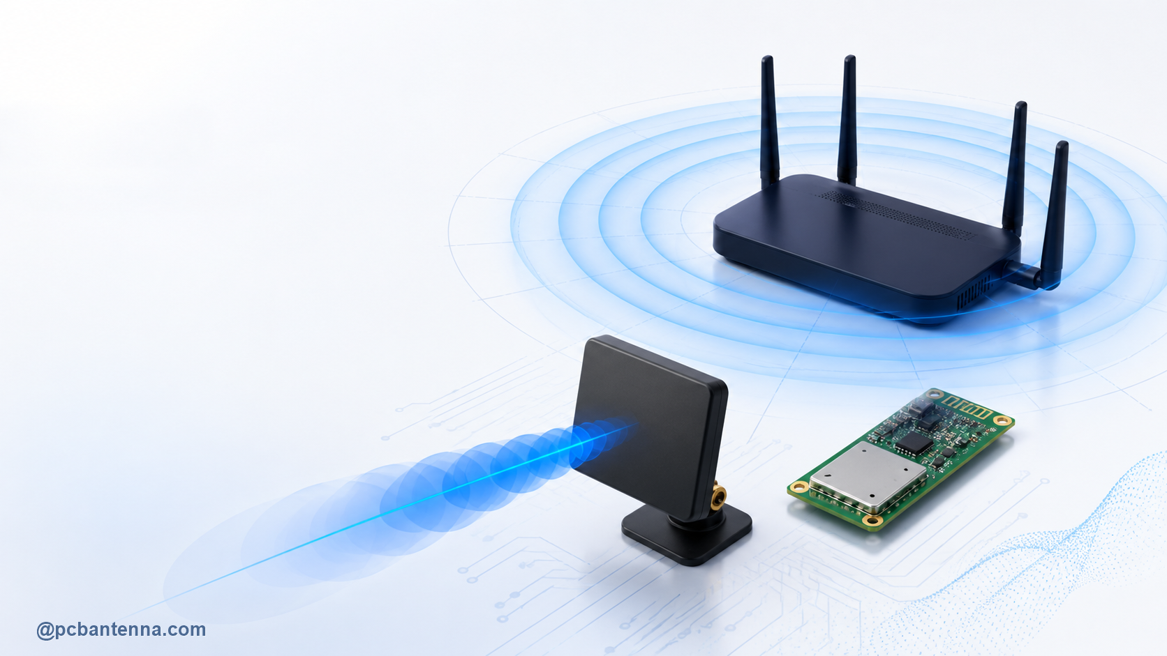
A good Wi-Fi antenna choice is rarely about finding the largest gain number. It is about putting enough signal in the directions where devices actually need it, while keeping the antenna practical for the board, enclosure, and product use case. A compact sensor near an access point, a wall-mounted access point, and a long corridor link can all need very different antenna patterns.
This guide explains how Wi-Fi antenna types, gain, directionality, placement, and PCB integration work together. It is written for engineers building Wi-Fi-enabled products, not just for choosing an external antenna after the board is finished.
A Wi-Fi antenna transmits and receives RF energy for a wireless link. The product may operate in the 2.4 GHz, 5 GHz, or 6 GHz Wi-Fi bands depending on its radio, antenna, regional approval, and intended standard. The important design question is not simply “Which Wi-Fi antenna is best?” It is: where will the other device be relative to this product, and how much change in orientation or environment must the link tolerate?
Write down the real installation condition before comparing parts. Is the device on a desktop, a ceiling, a metal machine, or a wall? Is the receiver moving? Does coverage need to be broad and local, or aimed toward one remote area? Are there walls, racks, people, batteries, or cables near the antenna? Those details are what turn an antenna specification into a working product decision.
The two broad Wi-Fi antenna types are omnidirectional and directional. An omnidirectional antenna is designed for broad coverage around a chosen axis. It is often a sensible starting point for a mobile device, an access point serving a room, or an embedded product whose user can approach from several sides. “Omnidirectional” does not mean equal radiation everywhere in 3D. Most real antennas still have weak directions and nulls.
A directional antenna concentrates more of its useful radiation toward a target area. Panel, patch, Yagi-type, and some array antennas are common examples. Directional coverage can be useful for a point-to-point link, a long aisle, a specific work cell, or an outdoor connection where radiation behind the antenna is not useful. The trade-off is simple: a stronger forward beam usually comes with less forgiving coverage away from that beam.
TE Connectivity’s overview of Wi-Fi antenna technology likewise distinguishes broad-coverage omnidirectional antennas from focused directional antennas. Treat that as the start of the decision, not the end. The finished enclosure and mounting position can change the pattern significantly.
Gain tells you how strongly an antenna radiates or receives in a stated direction compared with a reference. More gain does not create transmitter power; it redistributes available energy. In practice, a higher-gain directional antenna often has a narrower main beam. That can improve a known link path, but it can also make a product less reliable when it is turned, tilted, or moved.
Always read gain with the radiation pattern. A 5 dBi specification may be useful when the receiver is in that main lobe and disappointing if the receiver sits in a null. The antenna gain guide explains dBi, efficiency, directivity, and realized gain in more depth. Our radiation pattern guide shows how to read the lobes, beamwidth, and weak directions behind the headline gain value.
Placement is not a final mechanical detail. Nearby conductive material can alter antenna current paths, detune resonance, block radiation, or reshape the pattern. Keep the antenna clear of large ground interruptions, metal brackets, display frames, batteries, shield cans, and cable bundles when the selected antenna’s documentation calls for it. A cable routed across the antenna keepout can undo hours of matching work.
Orientation matters just as much. A vertical antenna and a horizontal client can suffer polarization mismatch. A wall-mounted device can direct most of its energy along the wall, into the room, or into the wall depending on antenna choice and installation. Before locking the enclosure, check the product in its intended orientation and at the likely receiver locations.
For a practical placement review, answer four questions: Where is the desired receiver? Where is the nearest metal? Which way will the product face? What is likely to change after installation? If the answers are uncertain, broad coverage and robust validation often matter more than a very high peak-gain value.
An embedded PCB antenna can save cost, volume, and assembly steps. It can be an excellent option when the board size, ground plane, keepout area, enclosure material, and tuning process are under control. It also keeps the RF path short and repeatable. The compromise is that it is more sensitive to PCB revision and product integration than a separately mounted external antenna.
An external antenna can place the radiating element away from a crowded board or metal enclosure and may give the mechanical team more flexibility. It also introduces connector, cable, durability, and assembly considerations. A long or poorly routed cable has loss; an exposed connector needs a reliable mechanical strategy. Neither option is automatically better. The right choice depends on the required pattern and on what the product can physically protect from the antenna.
If you are using an on-board trace, chip, or flex antenna, start with the PCB Antenna Design Basics guide. Follow the antenna vendor’s reference layout closely for the first prototype, including the specified ground plane and keepout. A generic footprint copied into a different board shape is not the same as the validated reference design.
These rules are connected. A feed line can look correct on a layout screenshot yet perform poorly if return current is interrupted by a split ground, via fence, or nearby opening. Use the Microstrip Line Calculator as an early design aid, then validate the actual stackup and geometry rather than relying on a generic default.
Many modern Wi-Fi products need more than one operating band, and some use multiple antennas for spatial diversity or multi-stream operation. That raises the integration difficulty. Each antenna needs suitable bandwidth and a stable pattern in the final enclosure, while the antennas also need enough separation and isolation for the radio architecture. The physical room available for an antenna may be the hardest constraint in a compact product.
Do not place two antennas as mirror-image artwork and assume the result will be independent. Check the radio module’s layout guidance, keep the intended antenna orientations clear, and model or measure the complete system. When multiple antennas are used, orientation, spacing, ground paths, and nearby materials become design variables.
Wi-Fi range depends on far more than antenna gain. Transmit power, receiver sensitivity, path loss, wall material, congestion, cable loss, polarization, fade margin, and the gain in the actual link direction all matter. A gain figure measured in a favorable direction cannot be dropped into a range claim without those other inputs.
Use the RF Link Budget Calculator and Free Space Path Loss Calculator for a transparent first estimate. The Wavelength Calculator can also help relate physical dimensions and spacing to the selected band. Then test in the installation environment, because walls, shelves, people, and multipath reflections are not free-space conditions.
The strongest Wi-Fi antenna design is the one that matches the product’s actual coverage requirement and stays predictable after integration. Define the directions that matter, choose the right pattern before chasing gain, protect the antenna in the PCB layout, and validate the final product rather than a bare board. For a custom design, simulation review, or an integration problem that needs a second set of eyes, explore our antenna design services or contact PCB Antenna.