Get "10 RF Design Principles Every Engineer Should Know" Free
Learn practical principles for better RF circuits, PCB layouts, simulations, measurements, and troubleshooting.

A practical antenna gain guide covering dBi, dBd, directivity, efficiency, realized gain, beamwidth, and link budget decisions.
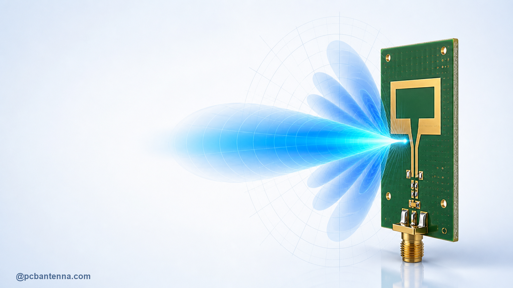
Antenna gain is one of the most quoted RF specifications and one of the easiest to misunderstand. A higher-gain antenna does not create extra transmitter power. It concentrates available radiated power more effectively in some directions, usually by taking coverage away from others. That can be exactly what a link needs, or it can create a frustrating dead zone if the product moves, tilts, or needs wide-area coverage.
This practical guide explains what antenna gain means, how dBi and dBd are used, how gain differs from directivity and efficiency, and how to use the number in a real RF design. The focus is on better engineering decisions rather than chasing the largest value on a datasheet.
Gain compares an antenna’s radiation in a chosen direction with a reference. The most common reference is an ideal isotropic radiator, a theoretical point source that radiates equally in every direction. Gain referenced to that source is written in dBi. An antenna with 3 dBi gain in a particular direction is radiating three decibels more strongly there than an isotropic source would for the same accepted input power.
The phrase in a particular direction matters. Gain is not a single, uniform property around an antenna. A radiation pattern has peaks, nulls, and often side lobes. A small omnidirectional antenna may have modest peak gain but useful coverage around the product. A panel or array may have much higher peak gain but only within a narrower beam.
dBi uses the ideal isotropic radiator as the reference. dBd uses an ideal half-wave dipole as the reference. Because an ideal half-wave dipole has about 2.15 dB more gain than an isotropic radiator in its strongest direction, a value in dBd is about 2.15 dB lower than the equivalent value in dBi. For example, 0 dBd is approximately 2.15 dBi.
Neither unit is inherently better. The problem appears when a specification omits the reference. If one supplier states gain in dBi and another uses dBd, the numbers cannot be compared directly. For PCB and RF work, dBi is common, but always read the label and ask whether the reported value is peak gain, average gain, realized gain, or a measurement in a specific orientation.
These four ideas are closely related but not interchangeable:
This distinction explains a common surprise: an antenna can have a sharp, directive-looking pattern and still deliver weak link performance if it is inefficient or badly matched. It can also show a good S11 curve and still underperform if losses are high or the strongest lobe points away from the receiver. Use S11 and return loss as a match diagnostic, but do not use it as the whole antenna scorecard.
In many antenna designs, more directional gain comes with a narrower main beam. This is not a universal one-line rule for every shape, but it is a useful physical trade-off to remember. When radiation is focused in one direction, less of it is available elsewhere. That is great for a fixed point-to-point link, a gateway aimed at a sensor field, or a panel antenna serving a known area. It can be poor for a wearable, handheld, or mobile product that needs coverage in many orientations.
Do not choose an antenna only from the peak gain number. Look at the full radiation pattern, especially the directions that matter in use. A product installed vertically may need horizontal-plane coverage. A device on a moving platform may need tolerance to tilt. A reader mounted on a wall may need a deliberate forward beam and low rear radiation. The right answer comes from the coverage requirement first, then the antenna topology.
Gain matters because it appears directly in a radio link budget. A basic received-power estimate starts with transmitter conducted power, subtracts cable and connector losses, adds transmit antenna gain in the receiver’s direction, subtracts path loss, then adds receive antenna gain in the transmitter’s direction. Polarization mismatch, body loss, enclosure detuning, and fading margin also matter in a real system.
For a quick first pass, use the RF Link Budget Calculator, Free Space Path Loss Calculator, and Antenna Gain Calculator. Keep the inputs honest. Use the gain in the actual link direction, include known cable losses, and do not assume a datasheet peak gain is available in every orientation of the finished product.
For a passive reciprocal antenna in the same frequency and polarization conditions, the directional behavior is the same in transmit and receive. An antenna that has more gain toward the horizon when transmitting also has more receiving sensitivity from that direction. This is useful when thinking about a two-way link: changing the antenna pattern changes both ends of the conversation if the antenna is used for both transmit and receive.
That does not mean the system behaves identically in every situation. The transmitter power, receiver sensitivity, noise environment, cable losses, and polarization may differ from one end to the other. Gain is one part of the system, and it earns its value when it is evaluated with the rest of the system rather than in isolation.
For a PCB antenna, the gain measured on a clean evaluation board may not survive integration unchanged. The board ground plane, battery, display, shield can, cable, plastic housing, and nearby user can alter current paths and block or absorb energy. In some products, a small enclosure change moves the pattern more than a trace-tuning change.
This is why a gain target should be tied to a defined test condition: frequency, board revision, enclosure state, antenna orientation, polarization, and direction. The PCB Antenna Design Basics guide covers the layout and ground-plane decisions that shape this result, while the antenna bandwidth guide explains another trade-off that often appears while tuning compact antennas.
Gain is normally determined from a calibrated measurement arrangement or from a full-wave electromagnetic simulation that models the antenna and its surroundings. In measurement, the antenna under test is compared against known references with carefully controlled distance, orientation, polarization, and reflections. In simulation, far-field results can provide directivity, gain, realized gain, and patterns, but only for the geometry and materials included in the model.
When reviewing a gain plot, ask a few plain questions: What frequency is this? Is the value peak gain or realized gain? Which cut plane is shown? Is the device inside its enclosure? Was the cable included or managed? What is the polarization? Those details tell you whether the number applies to your use case. The HFSS antenna simulation workflow explains how to turn a model into results that can be compared with hardware.
The best antenna gain is the amount of directional performance that solves the real link without creating a coverage problem somewhere else. If you need help comparing antenna options, validating a PCB antenna in its enclosure, or connecting gain results to a link budget, see our antenna design services or contact PCB Antenna.