Get "10 RF Design Principles Every Engineer Should Know" Free
Learn practical principles for better RF circuits, PCB layouts, simulations, measurements, and troubleshooting.

A practical beginner guide to PCB antenna design covering layout, ground planes, RF feeds, matching, simulation, and validation.

PCB antenna design looks deceptively simple. A short copper trace sits at the edge of a board, the radio sees a 50-ohm-looking feed, and the product is ready for wireless. In real hardware, that trace is only one piece of the antenna. The board ground, battery, display, enclosure, cable, nearby metal, and even how a customer holds the product can change the result.
This beginner-friendly guide explains the practical workflow behind a good PCB antenna design. It is not a substitute for a full electromagnetic model or compliance test, but it will help you make better choices before the first prototype and avoid the expensive mistakes that appear when RF is left until the end of the layout.
For a PCB antenna, current does not stop at the pretty copper shape. It returns through the ground structure and is influenced by nearby conductors and dielectric materials. That is why a reference antenna can work well on its evaluation board and poorly after being copied onto a smaller board with a battery next to it. The layout, board outline, ground plane, and enclosure all belong to the RF design.
This is also good news. You have more than one tuning lever. The radiating trace matters, but so do the antenna position, ground-plane dimensions, feed geometry, matching components, and mechanical arrangement. A disciplined process lets you use those levers one at a time instead of making random changes after the board arrives.
Start with the actual use case. Write down the operating band, required bandwidth, target range, data rate, board size, enclosure type, battery location, and expected device orientation. Add the environment too: an indoor sensor near walls behaves differently from an outdoor tracker or a Wi-Fi product carried in a pocket.
Frequency sets the first physical scale. A lower-frequency antenna generally needs more electrical length than a higher-frequency antenna, though loading and the surrounding structure can make the printed geometry much smaller than a simple straight-wire estimate. Use the Wavelength Calculator and Antenna Length Calculator for a quick starting point. Treat the outputs as engineering scale checks, not final production dimensions.
There is no universally best PCB antenna. A printed meander, inverted-F antenna, monopole, loop, chip antenna, patch, or external connector can all be the right answer in the right product. The useful question is: which option fits the frequency, board geometry, enclosure, cost, and performance target with enough room to tune?
A beginner-friendly rule is to choose the least risky topology that meets the product requirement. Do not force a tiny printed antenna into a design with no ground plane, no tuning access, and a long-range target simply because it looks neat in the CAD view.
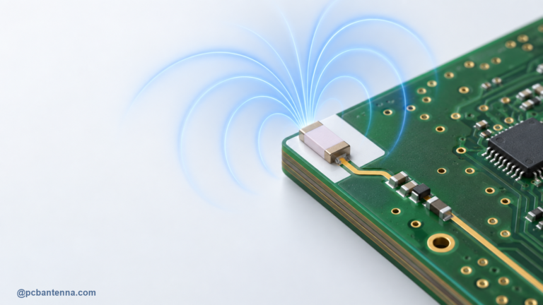
Board-edge placement is popular because it lets the antenna couple to open space rather than to a dense field of components. It also makes it easier to maintain a keepout around the radiator. A keepout usually means avoiding copper, traces, vias, components, shields, screws, batteries, and metalized plastic near the active antenna area. The required distance is not one universal number; it depends on frequency, topology, board layers, and the antenna vendor’s reference layout.
Keep high-speed digital routing and noisy switching circuits away from the antenna and feed. The reason is not only detuning. A receiver can lose sensitivity when noise couples into the RF path, even if the antenna is nominally resonant. If the product needs a display, camera, battery, or shield can close to the antenna, model those parts or at least reserve time for measured tuning with the final mechanical assembly.
Many compact antennas use the ground plane as a counterpoise or as part of the radiating system. A change to the ground outline can shift resonance, alter bandwidth, and reshape the radiation pattern. This is why splitting ground, creating large slots, adding a connector, or moving a battery can change antenna behavior even when the antenna trace was never touched.
Keep the antenna zone and the main ground structure intentional. Avoid an accidental ground island beside the radiator. If the radio requires a continuous return path, do not route the feed over a gap. If the antenna reference design expects a certain board length or ground clearance, preserve it until you have measurement data that supports changing it. The useful habit is simple: every time the mechanical or PCB team changes a large metal feature, review the antenna as well.
The feed line connects the radio to the antenna. At RF, it is not just a thin wire drawn in copper; it is a transmission line whose behavior depends on trace width, copper thickness, substrate, ground distance, and nearby copper. Many radios expect a 50-ohm environment, but the correct physical width for a 50-ohm microstrip or coplanar line depends on the actual board stackup.
Keep the feed short, continuous, and away from unnecessary vias and branches. Avoid sharp geometry changes where possible, and do not let unrelated signals run tightly beside it. Use the Microstrip Antenna Calculator as an early reference, then confirm the trace geometry against your board fabricator’s stackup information or a controlled-impedance calculation. The calculator gives a useful first pass; the board build details decide the final dimensions.
Even a well-designed antenna often needs a small amount of tuning after the first board is measured. Reserve a matching network footprint close to the antenna feed, commonly an L or Pi arrangement. The initial build may use a simple series link or leave some positions unpopulated, but the pads give you a controlled place to add or change components without cutting traces.
Matching should not be used to hide a major geometry problem. If the resonance is far from the target band, first ask whether the radiator, ground plane, or nearby structure is electrically too long, too short, or too heavily loaded. Use matching to refine a sensible antenna, then validate whether the change preserved efficiency and radiation performance. A deep S11 dip alone is not a complete success criterion.
A vector network analyzer is the standard first tool for checking feed match. It shows how much power is reflected at the antenna port across frequency. Our guide to S11 and return loss explains how to read that measurement and why calibration location matters.
After the match looks reasonable, check the things S11 cannot tell you by itself: efficiency, gain, radiation pattern, polarization, and the performance of the finished device. An antenna can be well matched and still radiate poorly because loss or unwanted coupling consumes the accepted power. At minimum, compare over-the-air range or received signal performance with the enclosure and battery installed. For a serious product, use an appropriate antenna measurement setup or a specialist test service.
Full-wave simulation can show current distribution, impedance, fields, and radiation patterns before a board is fabricated. It is especially useful for comparing antenna positions and seeing how large mechanical parts influence the design. But a simulation only knows what you put in the model. Leaving out the battery, metal frame, cable, or enclosure may make the result look cleaner than the shipped product.
Start with a model that answers one decision at a time: which board edge is better, whether the ground plane is large enough, or how a trace-length change moves resonance. Then compare the prototype to the model and adjust the assumptions. The UWB PCB Antenna Design and Simulation in HFSS article shows how simulation and tuning can work together in a practical flow.
Every antenna decision should connect back to the required wireless link. A small loss from enclosure detuning or polarization mismatch may be harmless in a short-range product and unacceptable in a long-range one. Use the RF Link Budget Calculator, Free Space Path Loss Calculator, and Antenna Gain Calculator to turn an antenna change into a system-level question: does the product still have enough margin where it will be used?
Good PCB antenna design is less about finding a clever trace and more about managing the full RF environment. Start early, protect the antenna zone, treat the ground and feed as active parts of the design, reserve tuning options, and validate the actual product. That approach is repeatable whether you are working on a simple sensor board or a more demanding wireless device. For a design review or project support, visit our antenna design services page or contact PCB Antenna.