Get "10 RF Design Principles Every Engineer Should Know" Free
Learn practical principles for better RF circuits, PCB layouts, simulations, measurements, and troubleshooting.

See how plastic enclosures, batteries, cables, and product hardware detune PCB antennas, plus a practical measurement and tuning workflow.
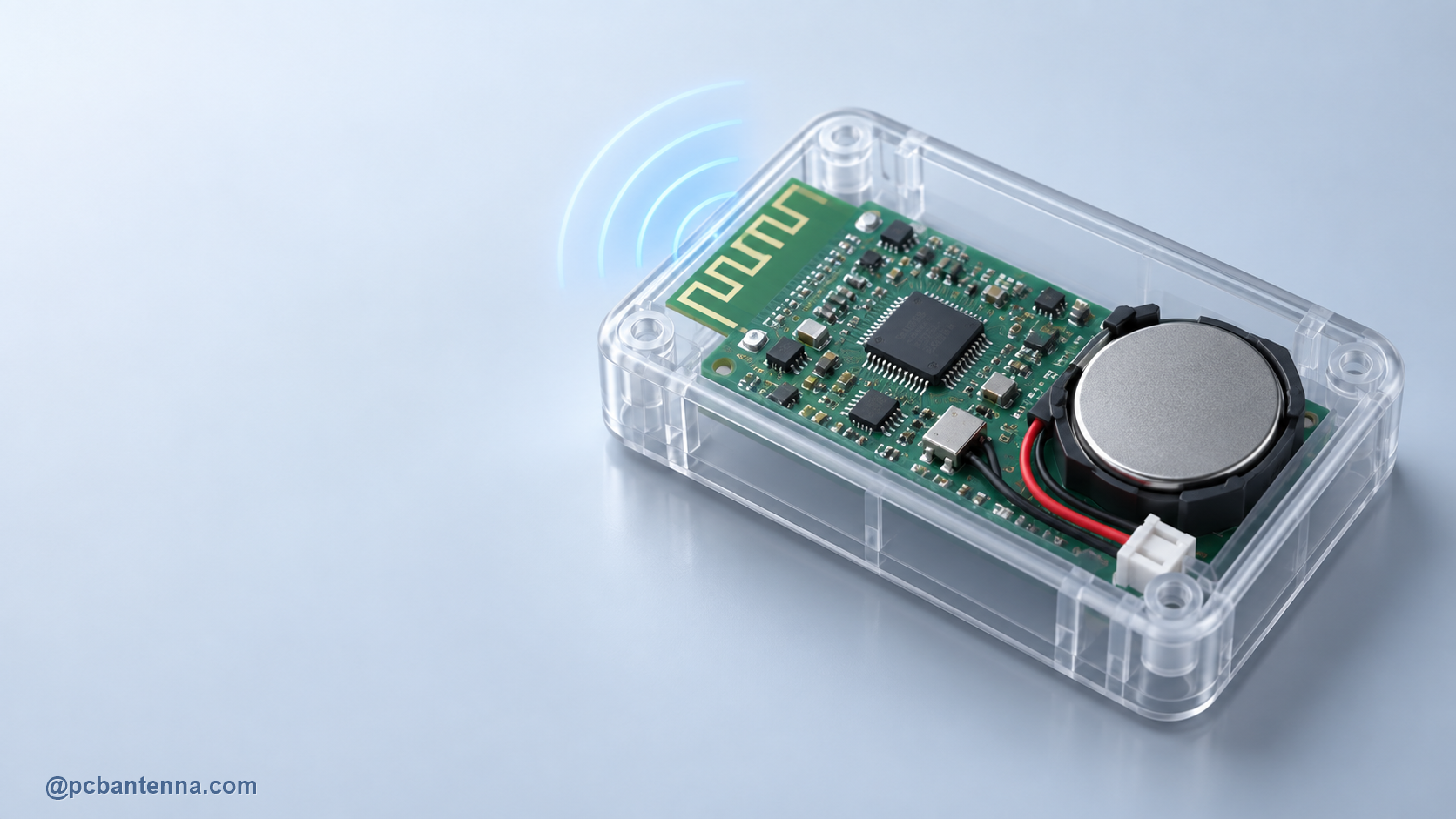
An antenna that works well on an open development board can change character as soon as it enters a product enclosure. Plastic, batteries, cables, display assemblies, and a user’s hand all change the environment around the radiator. This is antenna detuning: the resonant frequency, impedance, bandwidth, efficiency, or pattern shifts because the antenna is no longer seeing the same surroundings it had during the first test.
The frustrating part is that the radio can appear fine in a quick bench test. The issue may only show up after the battery is installed, the plastic cover is snapped on, or the product is held in a normal position. That is why a strong antenna workflow treats the enclosure and nearby hardware as design inputs, not as final packaging details.
Air and plastic do not affect fields in the same way. When plastic comes close to an antenna, the effective dielectric environment changes. For many compact antennas, that can increase electrical length and move the resonance lower in frequency. The amount of shift depends on the material, thickness, distance, antenna geometry, and how much field exists near that surface.
This is why copying a bare-board result into a finished product can be misleading. A thin enclosure with a generous gap may have a modest effect. A tight housing directly over a chip antenna may have a noticeable effect. There is no universal correction value worth memorizing. Measure the product configuration that customers will actually use.
A battery, metal bracket, shield can, or cable can couple strongly to a nearby antenna. The result can be a shifted match, reduced efficiency, more directional behavior, or inconsistent performance between assemblies. A coin cell directly under a radiator is a classic risk because it combines nearby metal with a large physical object relative to many small wireless boards.
Start placement early. Keep the antenna at the board edge when its reference layout recommends that location, reserve the required clearance on all layers, and place battery packs and cables away from the antenna region. Our antenna keepout guide explains how to protect that region in a layout tool.
These symptoms do not prove that the antenna is at fault. A power supply, firmware setting, test cable, or RF connector can also cause trouble. The value of a structured comparison is that it isolates one mechanical change at a time.
Measure the bare board first and save the trace. Then repeat the measurement with the intended battery, cable set, enclosure half, and final enclosure in place. Use the same calibration, cable routing, and reference plane for every run. If the product will normally be worn, handheld, wall-mounted, or installed near a metal surface, test representative positions as well.
Look beyond the deepest S11 dip. Check whether the usable match covers the required operating band and whether the response is repeatable across samples. Then check radiated performance if the product needs a specific range or direction. A good match does not guarantee a good radiation pattern.
First, follow the antenna supplier’s board size, ground pattern, feed, and clearance requirements. Leave a matching network footprint close to the antenna feed, even if the first prototype uses nominal component values. Keep the RF route short and controlled. Keep battery and microphone cables from crossing the antenna area. Avoid putting metal hardware directly above or below the radiator unless the antenna was designed for that configuration.
If space is tight, use simulation as a comparison tool rather than a promise. Model the bare board and major mechanical parts, then identify which nearby object produces the biggest change. This helps you decide whether to move the antenna, change the enclosure clearance, alter the board edge, or tune the matching network. The antenna bandwidth improvement guide is useful when detuning also narrows the usable band.
Tuning a prototype before the enclosure and battery are representative can create extra work. You may tune the bare board into a perfect match, then need to reverse the decision later. It is usually better to get the main mechanics close, preserve the tuning network, and make the final adjustment with the production-like assembly in place.
The same principle applies to vendor antenna data. It is a useful starting point, but it was measured on a particular reference board. Your board is a different electromagnetic object. Build the final decision around your own assembly and use a relevant RF calculator only for preliminary dimensions and link-budget checks.